Z80 Breadboard Computer
 |
Created: September 4, 2018 Updated: May 15, 2024 Latest revision: Rev 12a |
This project was inspired by the Zeta 256 and the Altair 8800 kit computer from the mid 1970's. Chip labels courtesy of Grant Searle and Upcycle Electronics.
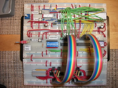
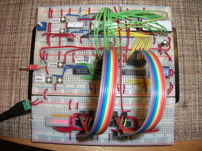
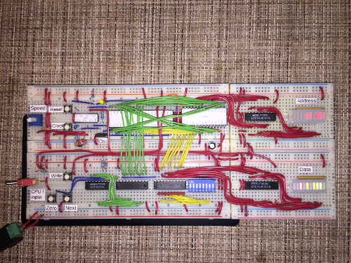
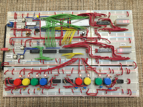
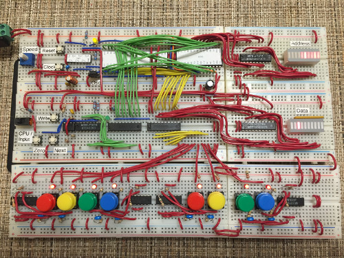
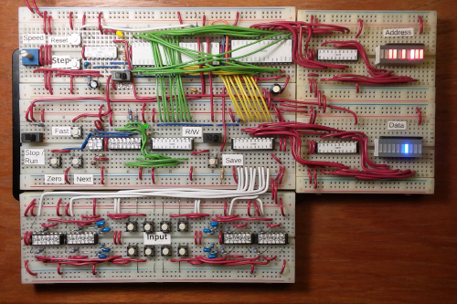
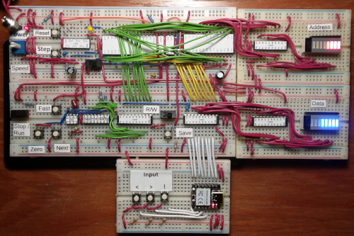
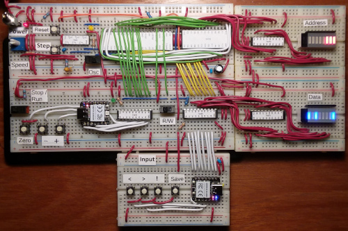
It is a minimalist computer based on a Zilog Z80 CPU and uses 256 bytes of a 32 KB static ram chip. The computer can be programmed and displays the contents of the Address and Data bus via two latched 10-segment LED bar displays (only eight segments are used).
Below is a description of the available pushbuttons and slide switches:
- Reset – Resets the CPU.
- Step – Tap to send individual clock pulses to the CPU.
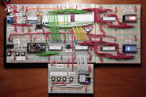
- Osc – Selects Single Step or Oscillator mode. In Oscillator mode, the Speed trim pot may be used to adjust the clock pulse frequency.
- Stop / Run – Selects Stop or Run mode. Programs can be entered in Stop mode. To run a program, select Run mode and press the Reset button.
- R/W – Selects Read or Write mode. The contents of the Address and Data busses may be viewed in Read mode. Programs may be entered in Write mode.
- Zero – Sets the Address bus to the start of memory.
- Down (-) / Up (+) – Press to decrease or increase the selected memory address. The button may be held down to advance repeatedly.
- Input – Programs may be entered when Stop mode and Write mode are enabled. The < and > buttons select the bit to the left or right and wrap around. The NOT (!) button toggles the bit on or off. Holding the button down will turn all bits off or on – this can help to speed data entry, depending on the value being entered.
- Save – Writes the byte indicated on the Data display to the selected Address.
Sample Animations
Left Sweep |
Left Sweep Receding |
Left Sweep Trailing |
Breathing |
Knight Rider |
Stack |
Revision History
Rev 2 – September 9, 2018
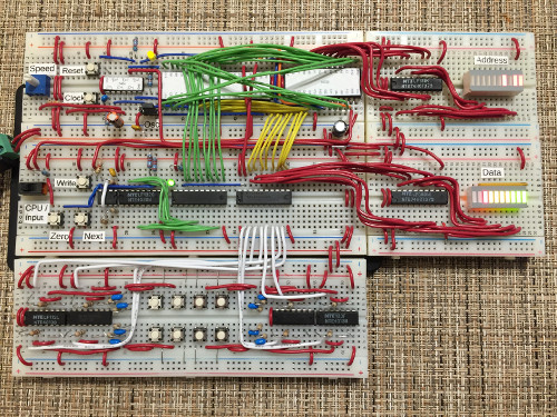
Replaced Address bus DIP switch block with a binary counter, to simplify data entry.
Rev 4 – September 22, 2018
Replaced Data bus DIP switch block with tactile push buttons, to further simplify data entry.
Rev 5 – September 29, 2018
Added a 555 Timer chip to allow the Address to be advanced automatically by holding down the Next button. It may also be tapped to step one byte at a time. Also replaced CPU toggle switch with slide switch for ease-of-use.
Rev 6 – October 4, 2018
Replaced clunky tactile switches with smaller Omron types. Since the state of the toggle switches can be seen on the respective 10-segment LED block while entering program code, the LEDS which were previously situated near the switches have been removed.
Rev 7 – October 5, 2018
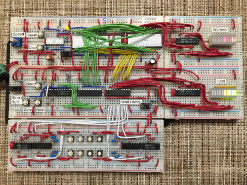
Added a Read / Write switch. When the computer is in Stop mode, this switch can be used to view the state of the input switches, or the contents of memory at the selected address – the latter option being useful for debugging.
Rev 8 – October 20, 2018
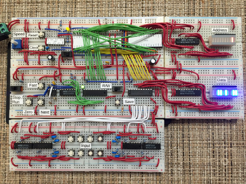
Added a Fast button to allow faster stepping between Address locations. Also replaced the 10-segment multi-color LED block with a blue variety.
| Rev 9 – May 5, 2024 | |
|
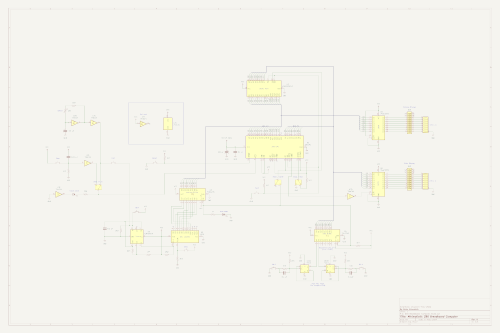
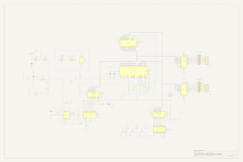
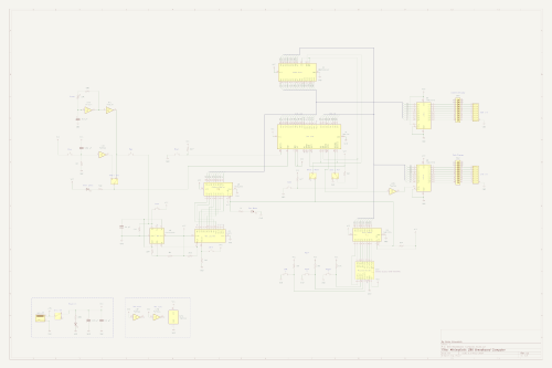
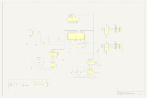
Finally got around to adding a schematic and I apologize to those who have been asking for one. If I knew how easy (and downright fun!) it is to create one using KiCad, I would have done this a long time ago. The Reset line is now pulled high by default and a momentary switch pulls it low. This negates the need to invert the signal (what was I thinking? 😄). Added more labels to the ICs. Chip count remains unchanged. |
|
| Rev 10 – May 8, 2024 | |
|
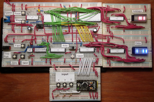
Replaced the Input section with a design that uses an OSEPP Pro Mini microcontroller instead of the four 4013 flip flop ICs used previously. The < and > buttons select the bit to the left or right and wrap around. The NOT (!) button toggles the bit on or off. Holding the button down will turn all bits off or on – this can sometimes help to speed data entry, depending on the value being entered. |
|
| Rev 11 – May 11, 2024 | |
|
Replaced the 24-pin OSEPP microcontroller with a 14-pin RP2040. Besides the much smaller footprint, it also has the advantage of USB-C connectivity instead of FTDI, for easier programming... and I think it's a lot easier on the eyes. 😁 The unused pin count is also down from 11 to just one (or none if you consider that it's for power). |
|
|
Rev 12 – May 13, 2024 There were a couple annoying drawbacks to using the 4020 binary counter with revs 3-11 of this project:
Since I already set a new precedent by using a microcontroller with the project, it seemed like a good time to give the banished OSEPP a new lease on life... at least until I can get my hands on another RP2040. 😁 So in this revision it is being used to control the Address lines. The Zero button still works the same. The minus (-) and plus (+) buttons decrease or increase the selected memory address. The button may be held down to move repeatedly. |
|
| Rev 12a – May 15, 2024 | |
|
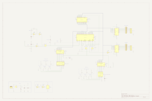
This revision uses matching RP2040 microcontrollers – one to control the Address bus and the other for the Data bus. |
|
|
Arduino sketch for Address microcontroller:
|
Arduino sketch for Data microcontroller:
|
